
A simple diy oscilloscope with arduino uno and mega Artofit
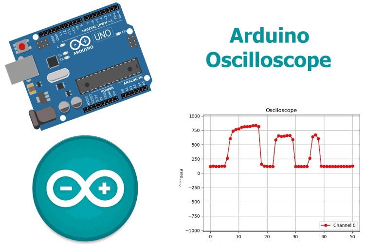
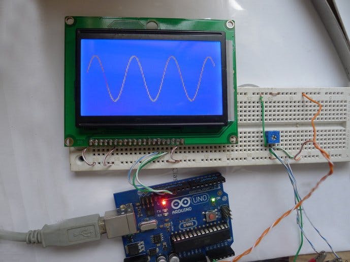
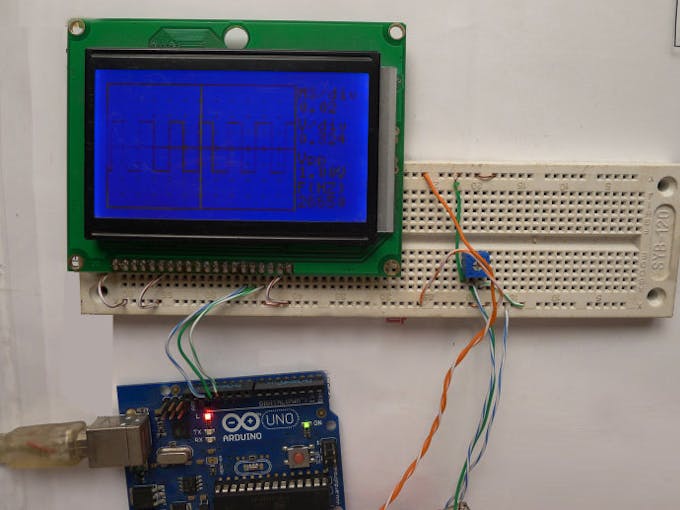
7.1 Ibrar Ayyub. Arduino Based Real-Time Oscilloscope. The Oscilloscope is one of the most important tools you will find on the workbench of any electronics engineer or maker. It is primarily used for viewing waveform and determining voltage levels, frequency, noise and other parameters of signals applied at its input that might change over.

Arduino oscilloscope tft
Arduino Based Real-Time Oscilloscope Make Your Own Arduino Based Real-Time Oscilloscope in a Step by Step Manner, learn and have fun Practicing Arduino. Updated on Dec, 2023 Language - English Ashraf Said. IT & Software,Hardware,Arduino. Lectures -18. Duration -1 hours . Add to Cart Buy.
How To Build An Arduino Oscilloscope Using OLED Display
Integers in the Arduino are 16 bits in size, which means we need to take our 10-bit results and shift them left until the top 8 bits contain our data. To do this, we shift our data left six times, which means we lose the lowest 2 bits of our ADC reading, but does not matter for our basic oscilloscope. With the 8-bit results sent, the last task.
Arduino Based RealTime Oscilloscope
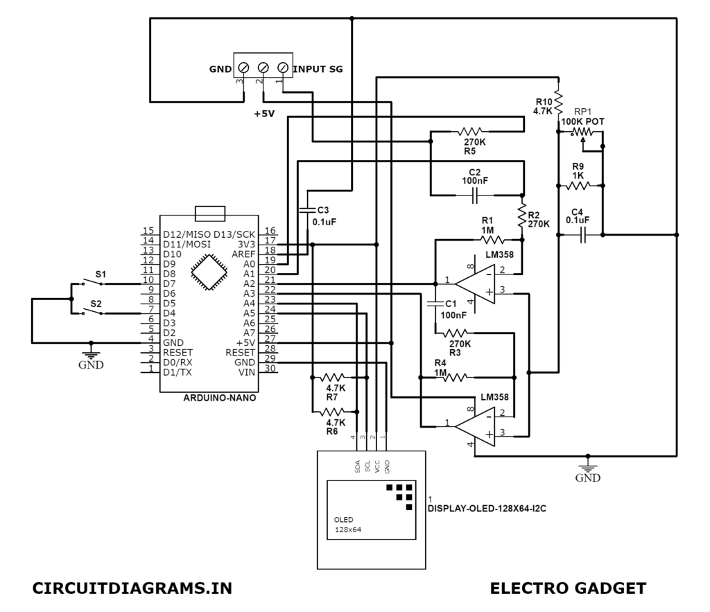
You can check them out if you are interested. In this article, we'll build a simple, low-cost Arduino-based oscilloscope with a 1.3" OLED display that can be used to visualize waveforms accurately. This project is inspired by Peter Balch Oscilloscope in a Matchbox project. We have changed a few codes and hardware to suit our requirements.

Arduino Based Dual Channel Digital Oscilloscope 18 Steps Instructables
Step 1: Story: I made 2 different oscilloscope and these are featured on this platform. And now I came up with an idea of dual channel oscilloscope. This one has main microcontroller as Arduino and 1.3" OLED display. This time I also have battery operating options and onboard charging circuit also.

ArdOsc is a matchboxsized, Arduino Nanobased oscilloscope Arduino Blog
Take your Arduino skills to the next level with this fun course! Learn step-by-step making Real-Time Oscilloscope. Discover the working principles of an oscilloscope, interface switches, and other devices with Arduino. You'll deal with sounds and tones, set outputs, and interface buttons with Arduino. Make your life easier using this tool. Start exploring to program, burn a code, and wire.

Create a Fast Arduino Oscilloscope YouTube
Install PCScope.exe program (developed by author) in your Windows PC and open the application. Next, open the Arduino sketch from Arduino IDE and compile the sketch. Connect the Arduino board to the PC and flash the sketch into the microcontroller on the Arduino board. Fig. 1: Circuit of the PC-based oscilloscope using Arduino.

How To Build An Arduino Oscilloscope Using OLED Display
Learn and have fun Practicing Arduino by Making Your Own Arduino Based Real-Time Oscilloscope in a Step by Step Manner Rating: 3.7 out of 5 3.7 (23 ratings) 3,843 students
Digital oscilloscope experiment based on Arduino Hackaday.io
Author. Arduino Based Real-Time Oscilloscope. The Oscilloscope is one of the most important tools you will find on the workbench of any electronics engineer or maker. It is primarily used for viewing waveform and determining voltage levels, frequency, noise and other parameters of signals applied at its input that might change over time.
Arduino Based RealTime Oscilloscope (2021) / AvaxHome
Arduino Based Real-Time Oscilloscope. Learn and have fun Practicing Arduino by Making Your Own Arduino Based Real-Time Oscilloscope in a Step by Step Manner. 4.4
Digital Oscilloscope Experiment Based on Arduino Hackster.io
a) The arduino "5V" level may not be accurate. Alter the spreadsheet b2-b3 values if you want strict accuracy. b) Reducing +-9V to 0-5V is a voltage drop of 18 to 5. one digit of our oscilloscope is 5*1000*1/255 = 19.6mV. An input change of 18*19.6/5 will cause a change in the analogue port.

Oscilloscope 3 Channel Arduino PC YouTube
This manipulation is about the Realization and the Simulation of a Low Cost Real-time #Arduino based #Oscilloscope with #Python GUI, Matplotlib and Drawnow l.

DIY ArduinoOscilloscope YouTube
The idea comes out while using my DSO138, a cheap oscilloscope you can find for $20, based on STM32F103. I was wondering what I can achieve with other Arduino compatible boards and some display I had available at home. I didn't plan to replace my DSO138, but just have fun.
Digital Oscilloscope Experiment Based on Arduino Arduino Project Hub
Temperature, Relay, Motion, Touch, GPS, CAN and Much More. Huge Range of Microcontroller Sensor Modules and Interface Boards

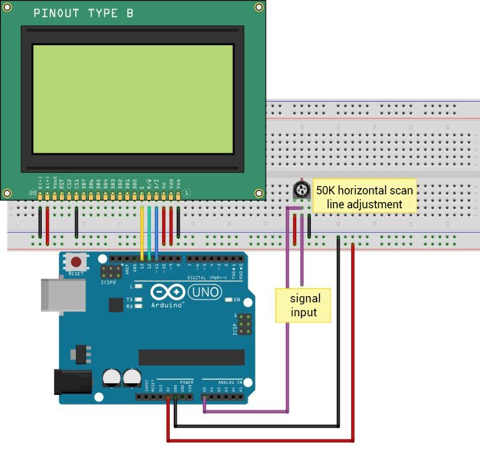
How to Create a Simple Oscilloscope With Arduino and Tft Lcd Arduino, Arduino projects
The most important feature for oscilloscope, except V/div, is T/div, or timing, that has to be as much precise as possible. This is why "standard" timing options based on TIMER1 were add to next version of software. There are 9 time settings Time/div (10 samples): 50ms, 20ms, 10ms, 5ms, 2ms, 1ms, 500us, 200us, 100usec. corresponding to.
Arduino usb oscilloscope
Step 1: Upload Arduino Oscilloscope Code. First of all you need some code to read the analog value from the analog input pin A0. You can do this easily by using the analogRead () function. Then you need to send this value over to your computer using the serial port. There are plenty of ways to do this. In the following code, the value is sent.
